Starter solenoid switch wiring diagram Vfd motor wiring diagram collection Variable speed drive block diagram
abb vfd wiring
Inverter diagrams vfd
Wiring a vfd to a momentary pushbutton switch (update)
Solenoid switch diagramAllen bradley limit switch wiring diagram [diagram] vfd bypass contactor wiring diagramVfd wiring diagram.
Understanding the wiring diagram for ac solenoid valves: a step-by-stepTest solenoid valve control circuits without shutting down the main system On video motor connection with vfd wiring diagramFile:vfd wiring diagram.jpg.

2 motors connected to 1 vfd,is there any way to have only one working
Connection motor drive diagram inverter delta star frequency variable connecting vfd wiring lh3 googleusercontent torque tightening maximum nmValve solenoid basics Brake wiring 3 phase motor vfdSolenoid valves versa bypass.
Solenoid switch wiring diagram 3Vfd control wiring diagram Connecting variable frequency drive to motorSo verdrahten sie einen 3-phasen-motor mit dem vfd.

Vfd wiring diagram beat fi
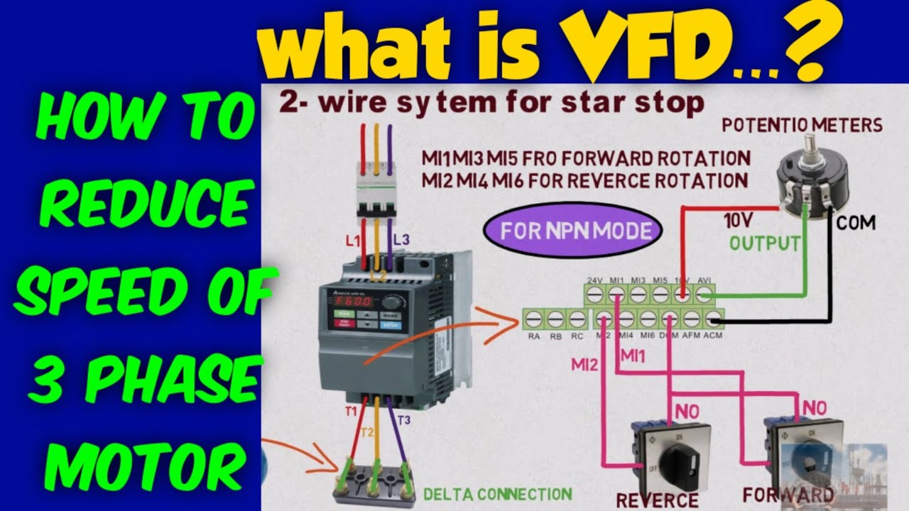
Vfd wiring inverterWhat is a vfd? Abb vfd wiringWiring motor diagram phase vfd drive frequency variable single inverter input speed output converter 4kw collection driver trane ecm database.
Solenoid series valves parallel valve switch level relay control liquid switches[diagram] hoa switch wiring diagram 3 phase motor control Vfd for constant pressure water supply systemDual battery solenoid wiring diagram.

Switch wiring vfd pushbutton momentary update machinist hobby reverse run
Wiring diagram vfd c17 manual file probotix wiki july[diagram] abb vfd control wiring diagram Vfd motorsandcontrol uses indicators abbVfd starter panel wiring diagram.
Motor auto/mannual connection with vfd & dol starter! 3 phase motorVfd control wiring with diagram 12 volt solenoid switch wiring diagramVfd wiring.
![[DIAGRAM] Vfd Bypass Contactor Wiring Diagram - MYDIAGRAM.ONLINE](https://i2.wp.com/www.csemag.com/wp-content/uploads/sites/5/2012/12/CSE1212VFD03-565x1024.jpg)
Vfd schematic symbol autocad electrical
Vfd wiring diagram with motor, switches, and external devices .
.